

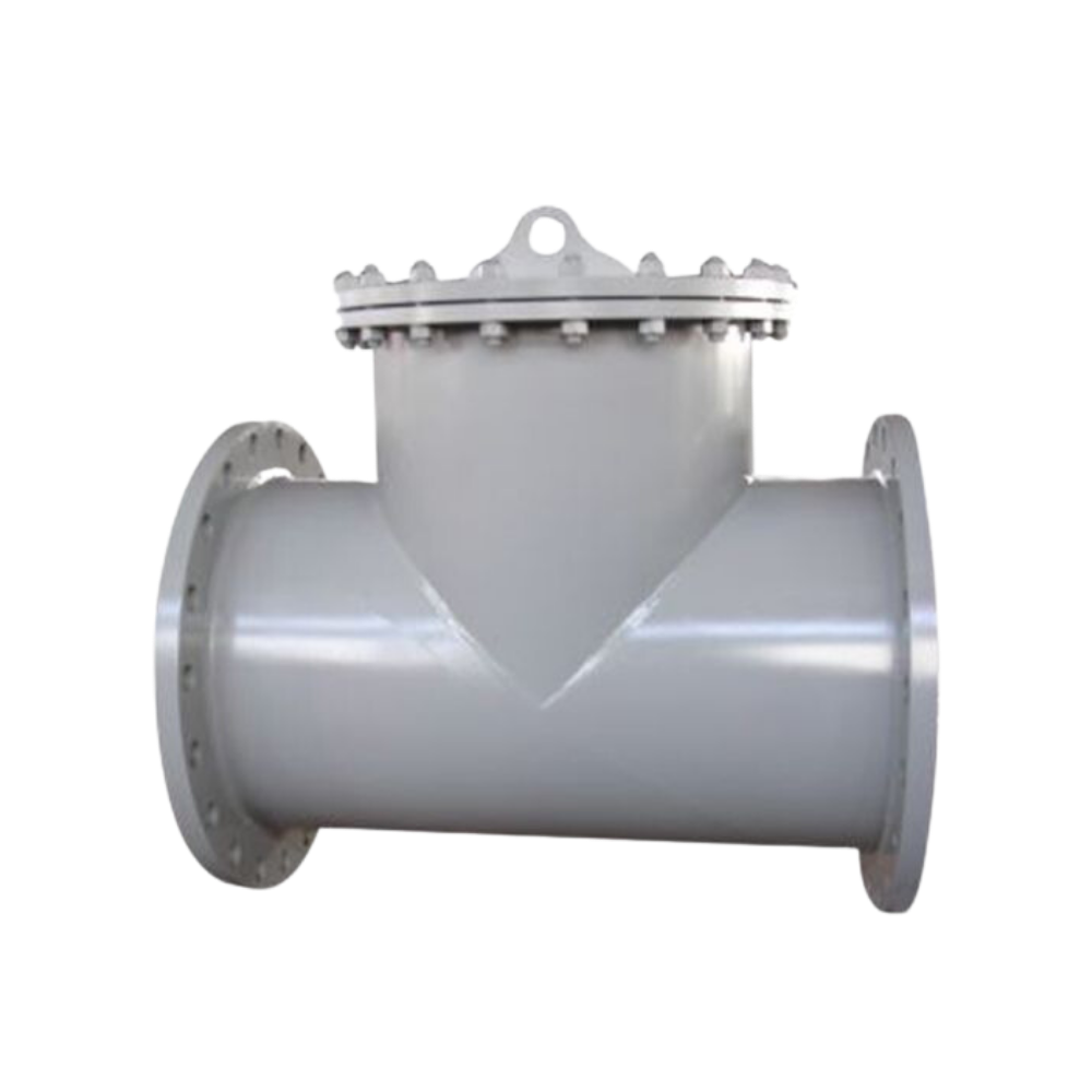


Lianke Valves’ T strainers (tee strainers) provide robust pipeline protection by filtering debris like rust, weld slag, and particulates in industrial fluid systems. Designed for inline installation, these T-type strainers safeguard pumps, valves, and downstream equipment from clogging and damage, outperforming cast Y strainers in flow efficiency while maintaining cost-effective coarse filtration.
Material Specification
| Nominal Diameter | Applicable to all specifications | |||
| Nominal Pressure | For each pressure | |||
| No. | Name | Material Lists | ||
| 1 | Inlet Flange | Q235/20# | 304 | 316L |
| 2 | Body | Q235/20# | 304 | 316L |
| 3 | Outlet Flange | Q235/20# | 304 | 316L |
| 4 | Skew Plate | Q235/20# | 304 | 316L |
| 5 | Strainer | 304 | 304 | 316L |
| 6 | Middle Flange | Q235/20# | 304 | 316L |
| 7 | Gasket | flexible graphite, Metal Spiral Wound Gasket | ||
| 8 | Middle flange cover | Q235/20# | 304 | 316L |
| 9 | Bolt nut | B7.2H | B8.8 | B8.8 |
Note: the above materials are conventional materials. If you need special materials, please contact in advance.
Technical Specifications
| Design&Manufacture Standard | SH/T 3411-2017 |
| Face-to-face Dimension Standard | SH/T 3411-2017 |
| Flange Standard | GB/T 9119-2008JB/T 81-2015HG/T 20592-2009EN 1092-1ASME B16.5HG/T 20615-2009 |
| Nominal Diameter | Applicable to all specifications |
| Nominal Pressure | For each pressure |
| Test Pressure | 1.5 times design pressure |
| Filtering Accuracy | 5 mesh – 300 mesh (4mm~0.05mm) |
| Temperature Range | 0~300℃ |
| Applicable Medium | Water, steam, oil and other media |
Note: if non-standard customization is required, please explain in advance.

HG/T 20592-2009 PN10 Unit:mm
| DN | L | H | H1 | D | D1 | D2 | D3 | N-I | f | B | N3 |
| DN40 | 204 | 123 | 250 | 48 | 150 | 110 | 88 | 4-18 | 2 | 18 | – |
| DN50 | 218 | 130 | 270 | 57 | 165 | 125 | 102 | 4-18 | 2 | 19 | – |
| DN65 | 246 | 144 | 305 | 76 | 185 | 145 | 122 | 4-18 | 2 | 20 | 1/2 |
| DN80 | 272 | 159 | 340 | 89 | 200 | 160 | 138 | 8-18 | 2 | 20 | 1/2 |
| DN100 | 314 | 180 | 390 | 108 | 220 | 180 | 158 | 8-18 | 2 | 22 | 1/2 |
| DN125 | 358 | 204 | 450 | 133 | 250 | 210 | 188 | 8-18 | 2 | 22 | 3/4 |
| DN150 | 396 | 223 | 510 | 159 | 285 | 240 | 212 | 8-22 | 2 | 24 | 3/4 |
| DN200 | 480 | 267 | 620 | 219 | 340 | 295 | 268 | 8-22 | 2 | 24 | 3/4 |
| DN250 | 572 | 315 | 740 | 273 | 395 | 350 | 320 | 12-22 | 2 | 26 | 3/4 |
| DN300 | 664 | 361 | 860 | 325 | 445 | 400 | 370 | 12-22 | 2 | 26 | 3/4 |
HG/T 20592-2009 PN16 Unit:mm
| DN | L | H | H1 | D | D1 | D2 | D3 | N-I | f | B | |
| DN40 | 204 | 123 | 250 | 48 | 150 | 110 | 88 | 4-18 | 2 | 18 | |
| DN50 | 218 | 130 | 270 | 57 | 165 | 125 | 102 | 4-18 | 2 | 19 | |
| DN65 | 246 | 144 | 305 | 76 | 185 | 145 | 122 | 8-18 | 2 | 20 | |
| DN80 | 272 | 159 | 340 | 89 | 200 | 160 | 138 | 8-18 | 2 | 20 | |
| DN100 | 314 | 180 | 390 | 108 | 220 | 180 | 158 | 8-18 | 2 | 22 | |
| DN125 | 358 | 204 | 450 | 133 | 250 | 210 | 188 | 8-18 | 2 | 22 | |
| DN150 | 396 | 223 | 510 | 159 | 285 | 240 | 212 | 8-22 | 2 | 24 | |
| DN200 | 480 | 267 | 620 | 219 | 340 | 295 | 268 | 12-22 | 2 | 26 | |
| DN250 | 572 | 315 | 740 | 273 | 405 | 355 | 320 | 12-26 | 2 | 29 | |
| DN300 | 664 | 361 | 860 | 325 | 460 | 410 | 370 | 12-26 | 2 | 32 |
HG/T 20592-2009 PN25 Unit:mm
| DN | L | H | H1 | D | D1 | D2 | D3 | N-I | f | B | N3 |
| DN40 | 204 | 123 | 250 | 48 | 150 | 110 | 88 | 4-18 | 2 | 18 | – |
| DN50 | 224 | 135 | 280 | 57 | 165 | 125 | 102 | 4-18 | 2 | 20 | – |
| DN65 | 260 | 155 | 330 | 76 | 185 | 145 | 122 | 8-18 | 2 | 22 | 1/2 |
| DN80 | 288 | 171 | 360 | 89 | 200 | 160 | 138 | 8-18 | 2 | 24 | 1/2 |
| DN100 | 340 | 197 | 425 | 108 | 235 | 190 | 162 | 8-22 | 2 | 26 | 1/2 |
| DN125 | 384 | 221 | 485 | 133 | 270 | 220 | 188 | 8-26 | 2 | 28 | 3/4 |
| DN150 | 436 | 249 | 555 | 159 | 300 | 250 | 218 | 8-26 | 2 | 30 | 3/4 |
| DN200 | 516 | 291 | 665 | 219 | 360 | 310 | 278 | 12-26 | 2 | 32 | 3/4 |
| DN250 | 608 | 339 | 785 | 273 | 425 | 370 | 335 | 12-30 | 2 | 35 | 3/4 |
| DN300 | 692 | 383 | 890 | 325 | 485 | 430 | 395 | 16-30 | 2 | 38 | 3/4 |
HG/T 20615-2009 150LB Unit:mm
| DN | L | H | H1 | D | D1 | D2 | D3 | N-I | f | B | N3 |
| DN40 | 238 | 139.9 | 285 | 48.3 | 125 | 98.4 | 73.0 | 4-16 | 2 | 15.9 | – |
| DN50 | 256 | 150.5 | 310 | 60.3 | 150 | 120.7 | 92.1 | 4-18 | 2 | 17.5 | – |
| DN65 | 296 | 173.7 | 365 | 76.1 | 180 | 139.7 | 104.8 | 4-18 | 2 | 20.7 | 1/2 |
| DN80 | 312 | 183.3 | 390 | 88.9 | 190 | 152.4 | 127.0 | 4-18 | 2 | 22.3 | 1/2 |
| DN100 | 364 | 209.3 | 450 | 114.3 | 230 | 190.5 | 157.2 | 8-18 | 2 | 22.3 | 1/2 |
| DN125 | 426 | 240.3 | 525 | 139.7 | 255 | 215.9 | 185.7 | 8-22 | 2 | 22.3 | 3/4 |
| DN150 | 464 | 260.9 | 575 | 168.3 | 280 | 241.3 | 215.9 | 8-22 | 2 | 23.9 | 3/4 |
| DN200 | 560 | 312 | 705 | 219.1 | 345 | 298.5 | 269.9 | 8-22 | 2 | 27.0 | 3/4 |
| DN250 | 636 | 351.6 | 810 | 273 | 405 | 362.0 | 323.8 | 12-26 | 2 | 28.6 | 3/4 |
| 738 | 404.2 | 940 | 323.9 | 485 | 431.8 | 381.0 | 12-26 | 2 | 30.2 | 3/4 |
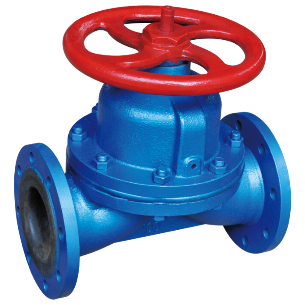
A weir-type diaphragm valve is a specific design of diaphragm valve that features a raised lip or saddle in the valve body. The diaphragm comes into contact with this weir to form a seal and control fluid flow. Main parts and materials Name/Material CI WCB CF8 CF3 CF8M CF3M Body CI WCB CF8 CF3 CF8M CF3M Diaphragm […]
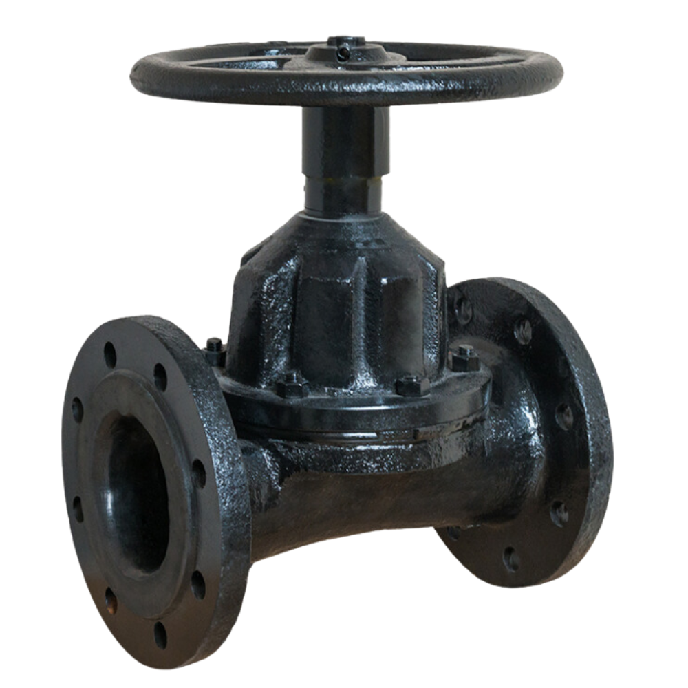
A straight-through diaphragm valve controls fluid flow in a pipeline using a diaphragm that moves vertically to open or close the flow path. The straight-through design allows fluid to pass directly through the valve, reducing pressure drop and maintaining efficient flow. It is commonly used in applications where reliable sealing and minimal obstruction are needed, […]
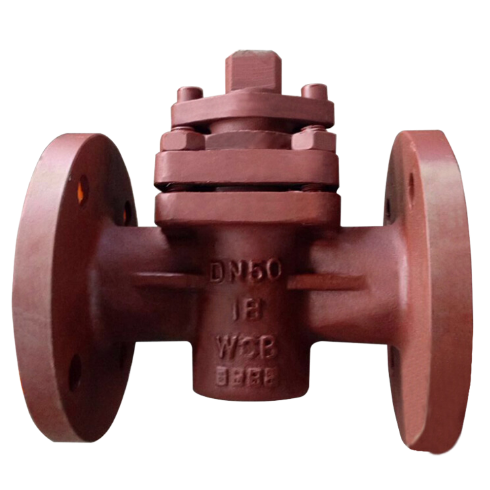
A plug valve controls fluid flow in a pipeline using a cylindrical or tapered plug with a central hole. The plug rotates within the valve body to open or close the flow path. When the plug aligns with the pipeline, fluid passes through. When turned so the hole is perpendicular to the flow, it blocks […]
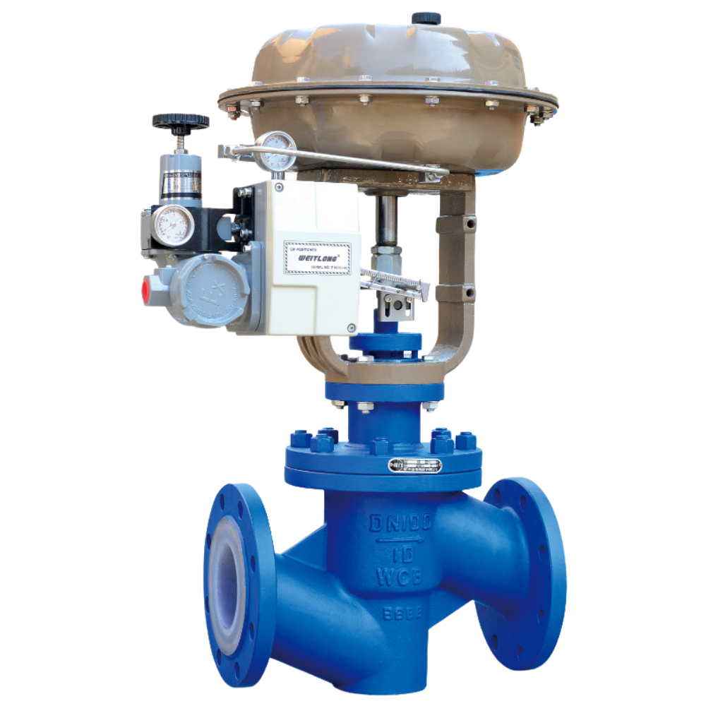
A fluorine lined control valve regulates the flow of fluids in a pipeline, adjusting flow rate, pressure, and temperature. It works by changing the size of the flow passage using elements like plugs, balls, or diaphragms. Control valves are crucial in industrial processes for maintaining operating conditions and ensuring system efficiency. They can be operated […]