

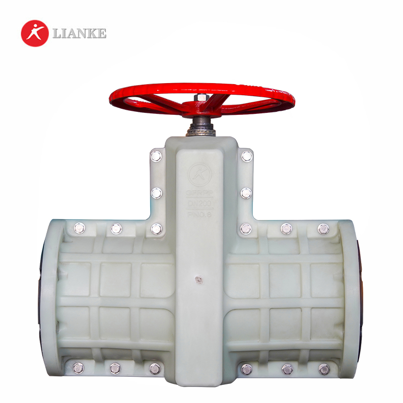


Lianke Valves’ pinch valves deliver unmatched reliability in controlling abrasive, corrosive, and slurry media across industries. Engineered for durability and cost-efficiency, these pinch valves feature a robust design with a replaceable rubber sleeve that ensures zero-leakage shutoff and full-bore flow, eliminating clogging risks even with granular or viscous fluids.
| Rubber quality | Application examples | Temperature range | Typical media |
| EPDM | Chemical applications: Applicable to 75% of all industrial chemical applications. | -40℃ – +110℃ | Concentrated and oxidiziing chemicals. |
| NR | High wear applications. | -40℃ – +80℃ | Abrasive materials, diluted acids, alkali & chemicals. |
| NBR | Applications involving oils, fats and hydrocarbon. | -30℃ – +100℃ | Oil, fats, fuels hydrocarbon, lubricants. |
| CR | Special-purpse chemical application: Resilient to ozone and averse weather | -40℃ – +100℃ | Chemicals, acids, several solvents, aliphatic oils, fats, lubricants |
| IIR | Special-purpse chemical application: Impermeable to gas | -40℃ – +100℃ | Concentrated and acidic chemicals, vegetable oil. |
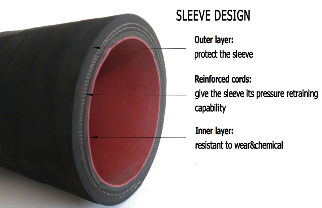
| Name | Material |
| Body | Aluminium alloy, Cast iron, Cast steel, Stainless steel |
| Sleeve | NR, EPDM, NBR, CR, IIR |
| Stem | Carbon steel, Stainless steel, Alloy steel |
| Pinch rod | Ductile iron |
| Side guide rod | Carbon steel, Stainless steel, |
| Hand wheel | Cast iron |
| Acceptable other special requirements of the material | |


Main dimension (mm)
| DN | PN(Bar) | L | L1 | L0 | D | D1 | Z-ɸ | D0 | H |
| 25 | 1-16 | 145 | 124 | 31 | 115 | 85 | 4-14 | 120 | 150 |
| 32 | 1-16 | 160 | 145 | 40 | 135 | 100 | 4-18 | 140 | 174 |
| 40 | 1-16 | 180 | 157 | 50 | 145 | 110 | 4-18 | 140 | 186 |
| 50 | 1-16 | 210 | 160 | 60 | 160 | 125 | 4-18 | 160 | 205 |
| 65 | 1-16 | 250 | 199 | 74 | 180 | 145 | 4-18 | 160 | 238 |
| 80 | 1-16 | 300 | 222 | 88 | 195 | 160 | 4-18 | 200 | 241 |
| 100 | 1-16 | 350 | 250 | 106 | 215 | 180 | 8-18 | 240 | 301 |
| 125 | 1-10 | 430 | 318 | 134 | 245 | 210 | 8-18 | 280 | 360 |
| 150 | 1-10 | 500 | 350 | 158 | 280 | 240 | 8-23 | 320 | 405 |
| 200 | 1-6 | 645 | 446 | 206 | 335 | 295 | 8-23 | 560 | 545 |
| 250 | 1-6 | 800 | 516 | 256 | 395 | 350 | 12-23 | 560 | 632 |
| 300 | 1-4 | 940 | 562 | 304 | 440 | 400 | 12-23 | 620 | 741 |
| 350 | 1-4 | 840 | 500 | 460 | 16-23 | 700 | |||
| 400 | 1-4 | 915 | 580 | 525 | 16-25 | 750 |
Zero Leakage Guarantee: The pinch valve’s elastomer sleeve creates a hermetic seal, critical for hazardous or high-purity media in pharma, chemical, and FGD systems.
Abrasion Resistance: Perfect for handling sand, tailings, sludge, and other erosive materials in mining, power plants, and quarries.
Certified Performance: Compliant with ANSI, EN 1349, and ISO 9001 standards, ensuring reliability in mission-critical operations.
Pinch Valve Types: Everything You Need to Know for Effective Control
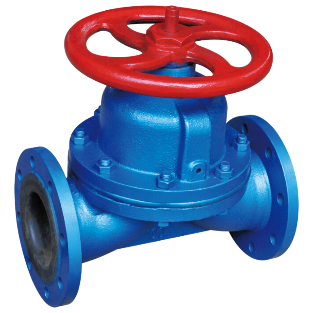
A weir-type diaphragm valve is a specific design of diaphragm valve that features a raised lip or saddle in the valve body. The diaphragm comes into contact with this weir to form a seal and control fluid flow. Main parts and materials Name/Material CI WCB CF8 CF3 CF8M CF3M Body CI WCB CF8 CF3 CF8M CF3M Diaphragm […]
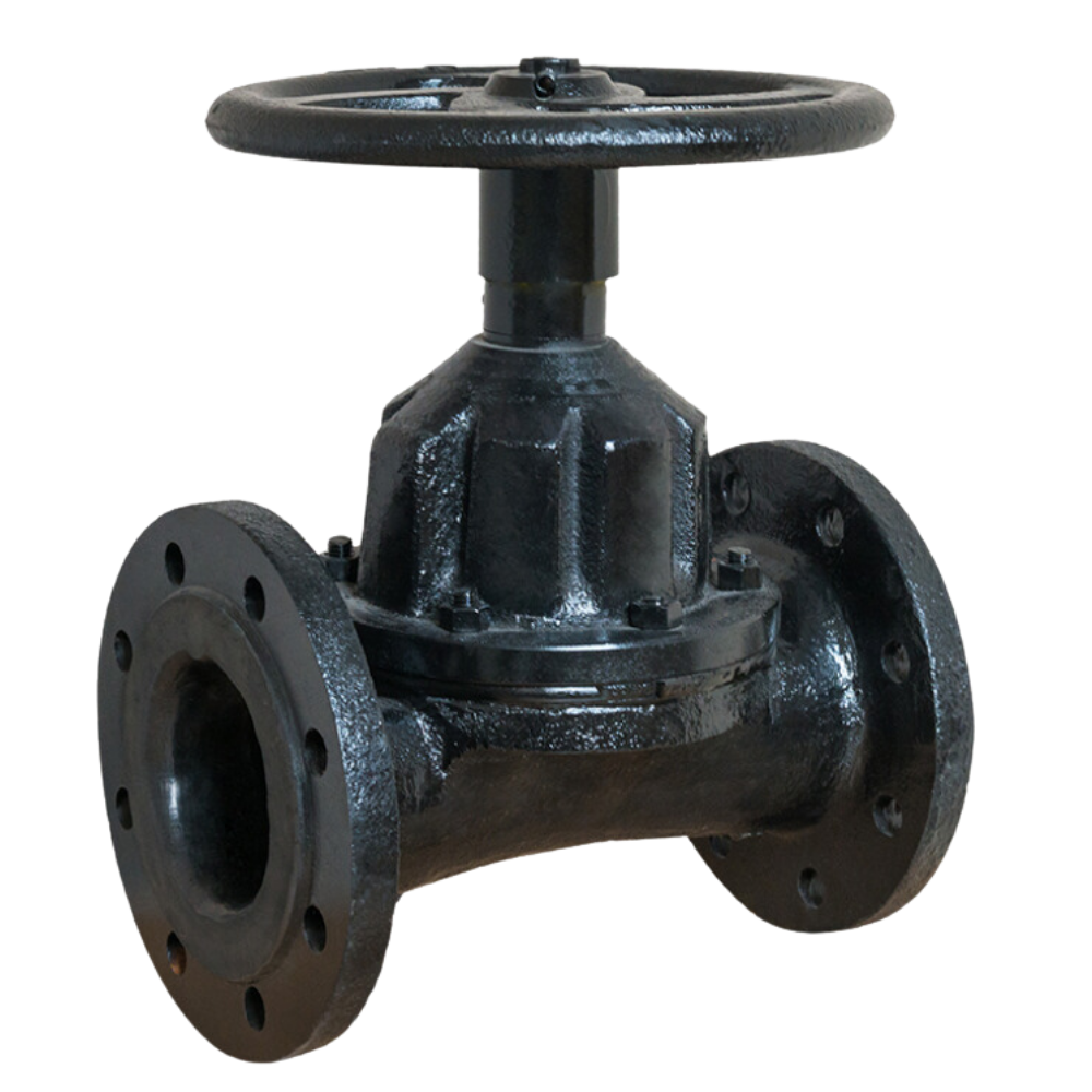
A straight-through diaphragm valve controls fluid flow in a pipeline using a diaphragm that moves vertically to open or close the flow path. The straight-through design allows fluid to pass directly through the valve, reducing pressure drop and maintaining efficient flow. It is commonly used in applications where reliable sealing and minimal obstruction are needed, […]
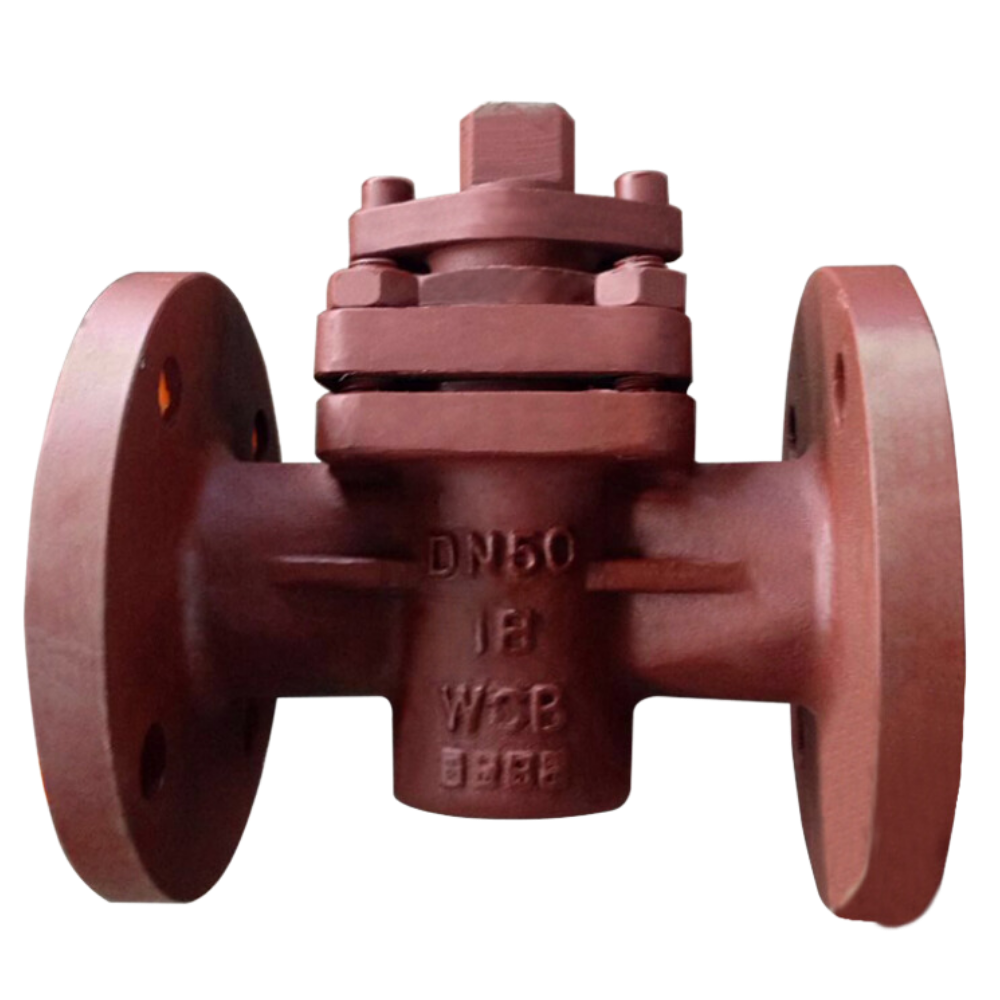
A plug valve controls fluid flow in a pipeline using a cylindrical or tapered plug with a central hole. The plug rotates within the valve body to open or close the flow path. When the plug aligns with the pipeline, fluid passes through. When turned so the hole is perpendicular to the flow, it blocks […]
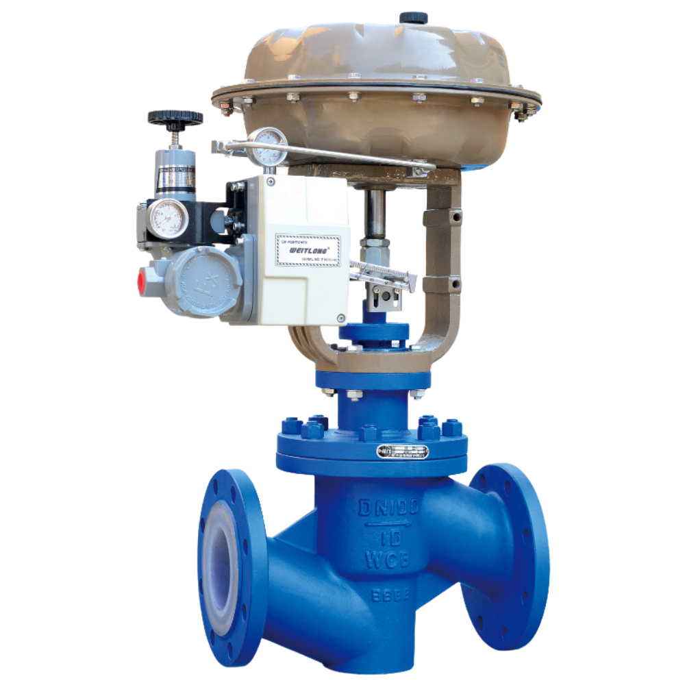
A fluorine lined control valve regulates the flow of fluids in a pipeline, adjusting flow rate, pressure, and temperature. It works by changing the size of the flow passage using elements like plugs, balls, or diaphragms. Control valves are crucial in industrial processes for maintaining operating conditions and ensuring system efficiency. They can be operated […]